Rudder connector ball and socket damaged

The friendliest place on the web for anyone who enjoys boating.
If you have answers, please help by responding to the unanswered posts.

timjet

Guru
Joined
Apr 9, 2009
Messages
1,920
The fixture that attaches my rudder to the tiller, something of a ball and socket device has broken. The top cap has broken off and am wondering if it's still safe to use.
The fixture is still solid and the ball is not loose in the socket nor can I pull it apart. Sorry don't know the name for this device. I hope the pictures will help idenitify it.
 

Attachments

  • rudder port a .jpg
    rudder port a .jpg
    27.1 KB · Views: 224
  • rudder connector 2 copy.jpg
    rudder connector 2 copy.jpg
    22.9 KB · Views: 286
The two questions that come to mind are what bent the cap, and why did the manufacturer install the cap?

Presumably the manufacturer had a good reason for installing the cap. I have no idea what it was, but it's rare that a manufacturer will stick on a component just for the fun of it. So my guess it was there to serve a purpose.

I suspect the reason it was bent is that the connecting rod was rotated by some force and with enough force for the socket on the end of the rod to bend one side of the cap up. I suspect that it is not normally supposed to do this. Or perhaps the cap is there to prevent the rod from rotating enough to allow the socket to pop off the ball.

In any event it seems obvious that something did not operate as designed and that the damage to the cap was the result. If the rod is being forced to rotate with enough pressure to bend the cap, then my take on it is that there is a problem with the steering system--- it's out of adjustment or something is sticking or is out of alignment--- and that this should be corrected before trusting your boat to what seems to me to be a definite problem.
 
I can't explain why the cap broke. Your reasoning is what I think too. The rod for some reason rotated up enough to allow the socket to come in contact with the cap and after several rotations or perhaps one large bump it broke off the cap. Actually I broke off the cap when removing the ball and socket device, but as the first picture shows it was badly bent and the reason I removed it. I can't explain why the rod would have rotated. When I examined it, there was no force causing the rod to rotate, but I was examining it when the boat was static.
Any idea what this is called or where to obtain a replacement.
 
Is your boat a single or twin? If it's a twin is the rod the torque tube that connects the two rudder bars together? If it is, I've also heard this tube called a tie rod, same as on a car. The ball and socket arrangment is generally called a ball joint, also like a car.

If your boat is a single, what is the other end of the rod connected to? And what is the threaded rod in the photo that connects to the rudder bar with the smaller ball joint? Is that an autopilot connecting rod? Or is it the connection from your steering system, which I'm guessing is hydraulic?* Or, since it's a pretty thin rod and is not attached to the point of maximum leverage, is it simply a connection to a rudder angle indicator or some sort of feedback connection to an autopilot?* (Obviously I'm just guessing here.)

And speaking of cars, as you may know, their tie rods and steering rods have similar ball-and-socket joints at their ends. Because of the geometry of the suspension and the way the components move, the rods do not maintain the same orientation which is why they need a ball joint at each end to compensate for the different rotational angles the rods can end up in. So..... if a component of your steering system is bent or out of alignment, it could be causing the tube with ball joint on the end to rotate more than normal, thus creating the pressure that bent the cap.

-- Edited by Marin on Monday 12th of July 2010 10:15:37 PM
 
timjet wrote: Any idea what this is called or where to obtain a replacement.

*
The piece that is missing is called a bolt head. The "cap" is called a washer. Hardware stores sell them by the each or the hundred in small boxes.

It appears that someone at some time overtorqued the bolt and fractured it just below the head. You will probably find some scratches on the underside of the washer where an attempt was made at some point to pry it up with a screwdriver in order to remove the bolt (or stud) from the Heim joint.

If your installation originally came with a stud, as it appears it may have, it had a socket head retainer where the washer is shown. You don't have to replace that, you can use a common bolt with enough grip length to ensure there are no threads in the ball and them use nuts as shown in your pictures to locate the height and secure the joint to the arm.*

I figure about 20 minutes work and $3 or less worth of parts. Make sure the ball moves freely and provide it with some waterproof lube once in a while.

Or, if the original was a stud, take a look at the offerings of this company:

http://www.midwestcontrol.com/buy.php?item=4766

-- Edited by RickB on Tuesday 13th of July 2010 07:15:39 AM


-- Edited by RickB on Tuesday 13th of July 2010 07:36:59 AM
 
Steering is considered a critical system and a new ball end shouldn't cost too much and the bolt used there could be a special purpose item. As an example an aircraft bolt is not as strong as other common fasteners but less likely to break as it's not so brittle. A long AN bolt can be tied in a knot and not break. Actually an AN bolt would probably be a good bolt for the ball end of a steering rod but the one the manufacturer selected may even be better yet. I'm quite sure the washer is there as a fail safe component like the chains on your trailer tongue. I'd just replace the ball end.

Eric
 
nomadwilly wrote:

I'd just replace the ball end.

*And you would then have two perfectly good ball ends with nothing to connect either one to the arm.
 
nomadwilly wrote:

*I'm quite sure the washer is there as a fail safe component like the chains on your trailer tongue.

I am willing to stick my neck out and say the the washer is there because someone lost the original socket head retainer and replaced it with a bolt and for some reason thought they needed a washer, then overtightened the bolt.

All*timjet has to do is take a fine file to clean up the broken end so it doesn't gouge the bore and drive the remains of the stud or bolt out toward the threaded part -*downwards if referring to the pictures. Like probably most of the boats running around, a carefully selected SS bolt of the proper grip length and fit will work nicely. There is no need for a washer on top either, the ball isn't going to fall out of the socket unless it has half an inch of slop. If it does then it should be replaced, otherwise all it needs is a bolt.
 
The boat is twin engine with 2 rudders connected by the black tie rod. The ends of the tie rod have the ball joint connected to it. The ball joints connect the tie rod to the rudder tiller. The tie rod is hydraulically actuated. The device in the first picture that Marian mentioned is a rod connected to a rudder sensor used by the autopilot.


As far as I can tell the ball joint seems intact even though the cap has broken off. I suspect the cap was bent some time ago. I will reuse the ball joint rather than make up a new assembly with bolts nuts, etc. I cant figure out what that cap is for, but again it has some purpose, perhaps to keep dirt and debris from the ball and socket, though I doubt this.


It certainly is possible as Rick suggests that the ball socket was over tighten or secured at such an angle that only slight rotation of the tie rod would force the socket against the cap. Rick, if it was a bolt with a washer that attached the ball joint to the tiller, the washer would have been too strong to break. It is not a bolt through the socket, it is a specially made ball joint, not just made up of locally purchased hardware items. The bolt is securely attached and I doubt I could get it out without damaging the ball and socket assembly. The cap that broke off is not a structural piece. It is easy to break off. Still not sure of its purpose.
And Rick, I will check with Midwest control products, it does look like they have something that will work.


Capn Chuck, your arrangement does not allow for the rotation of the hydraulic push rod. The tie rod due to the ball joints can rotate, something that for some reason is designed into my boat.


Thanks guys for taking an interest in this. The collective knowledge on this forum in invaluable.


-- Edited by timjet on Wednesday 14th of July 2010 06:52:23 AM

-- Edited by timjet on Wednesday 14th of July 2010 06:54:33 AM
 
Update:
I contacted the manufacturer of the ball joint, Marine Associates and they could not explain why the cap was installed. The replacement does not have a cap and Marine Associates thought perhaps that Carver specified that cap when ordering the part, again reasons unknown.
They also mentioned that probably many if not most boats with that ball joint installed probably have the cap laying in the bilge.
His recommendation; reinstall the ball joint. Proper name - tie rod end.
 
"... if it was a bolt with a washer that attached the ball joint to the tiller, the washer would have been too strong to break."

??

It was either a stud as shown in the Midwest Products photo, or a bolt that passes through the center bore of the ball. The bolt or stud might rotate in the ball and the ball is free to rotate axially and radially to compensate for the changes in geometry of the linkage as it moves.

If the threaded part you see below the ball were a machined extension of the ball itself, there would be no need for anything to retain the ball in the housing as it is not a "snap fit" like the little plastic rod ends you find on light duty extension arms and such, or the spring loaded retainers used on other low load assemblies.

I haven't seen everything but I will say that if you can't clean up the top of that ball with a fine file and push the stud out of the bore with relative ease, I will be very very surprised.

Simply putting it back on with nothing to retain the ball on the stud is an invitation to lose steering. Unless of course, it is*a special part machined by Marine Associates that is unique to their shop for reasons known only to them.*Ask them for a drawing and post it here.* So far, the pictures show a common run of the mill Heim joint type of ball connector.

Just had a look at the picture you posted. Is the rod bent where it enters the threaded portion of the assembly? If so, how did that happen? If so, make sure you check the rod for cracks, especially in the root of the thread at the point of bending.

-- Edited by RickB on Wednesday 14th of July 2010 08:23:20 AM
 
Rick,
I'm on a trip so I don't have the tie rod end in front of me. But from memory and looking again at the posted picture, the stud is probably pressed into the ball with the cap somehow attached to the top of the stud. The ball housing it appears is simply cast aluminum with an insert pressed in to hold the ball. That missing cap on the stud is so flimsy that even on a new one you could easy remove it with a pair of needle nose pliers something you could not do if it was a washer.*
In talking to the manufacturer, he said ignore it, the new one doesn't even have the cap installed. There is no way the manufacturer intended for that cap to hold the stud in place, it is just way to flimsy.*
I doubt you could push the stud out of the ball easily and if you use a hammer you would probably damage it in doing so.


-- Edited by timjet on Wednesday 14th of July 2010 09:05:51 AM
 
After reading RickB's description and looking at the first two photos again I, too, believe there is more missing from the setup than just the "cap." The top of vertical rod, the piece with the threads and the nut on the bottom, appears to have been sheared off. It never occurred to me that this rod could have started life as a bolt or as a stud with a fitting screwed down on the upper end of it. But it makes sense that it did, and that the "cap" is actually a simple washer as Rick said. Why this washer was stuck on the top of the ball joint instead of simply falling off when the top of the bolt/stud sheared I don't know.

But right now, going by your second photo with the "cap"/washer gone, there is nothing holding the ball part of the ball joint onto the top of the vertical bolt/stud running through it except the tightness of the fit.* I've never taken an automotive ball joint apart, I've just replaced them, so I don't know if the typical constuction has the vertical rod driven into the center of the ball or threaded into the ball.* I suspect it's driven but I could well be wrong.

But whether it's driven or threaded into the ball, there is now nothing to prevent the ball from either slipping up or perhaps unscrewing up over time under the pressures of steering the boat.* And when the ball comes off the top of the stud/bolt you will lose steering control over that rudder, and the tie rod could even drop down into the bilge and jam against something and take away all your steering control.* So you need to get a proper head back on the bolt/stud that runs through the ball.

Plus, assuming Rick's assessment is correct and that the vertical bolt or upper fitting on it was torqued to the point that the upper end of the bolt/stud sheared off, who knows what sort of stresses might have been put on the rest of it in the process. It could be something waiting to shear down lower under the pressures of steering.

If it was me I'd be looking to replace the whole deal and you'll have to if you can't get the ball joint off the remains of the bolt/stud.* The good news is that this should be a pretty simple fix assuming the proper sizes of hardware are available.

A point to remember regardless of how you deal with fixing the tie rod situation is that it's going to be important to preserve the alignment of the rudders if you replace the ball joint or remove the tie rod for surgery. Twin rudders are generally set to have a bit of toe-in or toe-out, they are generally not set to be exactly parallel to each other. This is to keep them from chattering and vibrating. So it might be a good idea to get the exact measurement from the center of one ball joint to the center of the other one before you take the tie rod apart so that if you do take the rod apart to fit new components you can adjust it to the exact length you have now before re-installing it. This will ensure that the rudders maintain their current alignment, which we will assume is correct.


-- Edited by Marin on Wednesday 14th of July 2010 12:28:09 PM
 
Marin wrote:

After reading RickB's description and looking at the first two photos again I, too, believe there is more missing from the setup than just the "cap." The top of vertical rod, the piece with the threads and the nut on the bottom, appears to have been sheared off. It never occurred to me that this rod could have started life as a bolt or as a stud with a fitting screwed down on the upper end of it. But it makes sense that it did, and that the "cap" is actually a simple washer as Rick said. Why this washer was stuck on the top of the ball joint instead of simply falling off when the top of the bolt/stud sheared I don't know.
Marin,Looking at the first picture you will see the tie rod end as it came from the factory with the bent cap. It is complete nothing missing. I know this because the other tie rod end is exactly the same except the cap is not bent. *Nothing has been sheared off. Looking closely at the first photo you will notice really two caps one inside the other. I believe the cap is actually one cap with an impression in it that gives the appearance of two caps. What probably happened is during adjustment either at the factory or later the cap was jammed up against the socket separating the cap into 2 parts at the indentation. An attempt was made to re-flatten the cap separating it further at the indentation and is probably why the inner cap is flanged up higher than the outer cap as shown in the first photo.


When I removed the tie rod end I tried to re-flatten the cap with my hand and it snapped off.


The vertical bolt has nothing attached to it at the top end except the cap. It is not a washer, way to flimsy and perhaps was designed to shear off, hence the indentation. In a call to the manufacturer they can't tell me why the cap was there and replacements don't have the cap.


I'm pretty sure the cap was damaged during adjustment and my guess is it came that way from the factory. There is no way the tie rod can rotate on one end and not the other, so if for some reason the tie rod were rotated beyond the limits of it's design, the other tie rod end would be damaged as well. It is not.


Marin, you paint a nightmarish picture of events that could happen if the tie rod end were to come apart. For this reason I will order a new one for peace of mind.


Thanks for your insight.
 
I would be interested to know how the bolt or stud is held to the inside of the ball joint. Is it just friction, is it threaded, or ?

Our own boat uses a somewhat simpler system. At the end of each rudder bar there is a heavy stud threaded into the bar. The tie rod ends have simple bronze "doughnuts" for want of a better word threaded into them and the hole fits snugly down over the smooth portion of the stud. Then a heavy bronze nut is screwed down onto the stud keep the "doughnut" in place and an identical nut is screwed down on top of the first one to lock it all together. I guess the alignment of the GBs rudder posts is such that the manufacturer felt there was no need for a ball joint.

Anyway the course of action you have decided to pursue seems to be the smartest, I think.
 
Marin wrote:I've never taken an automotive ball joint apart, I've just replaced them, so I don't know if the typical constuction has the vertical rod driven into the center of the ball or threaded into the ball.* I suspect it's driven but I could well be wrong.

*The ball joints under discussion have nothing in common with automotive ball joints. There is no comparison other than the name.

The ball is slightly flattened top and bottom and is bored through the center. The ball is retained within a spherical bearing that when formed during manufacture provides holding and bearing area from about *45N to *45S. If you were to play with one you would see that the ball is free to rotate inside the bearing and will rotate 360 degrees in any direction.

The body which holds the bearing has an internally or externally*threaded extension to provide a means to mount on the rod or fixture it serves. The center bore of the ball is designed to fit a standard diameter bolt or stud, though more precision assemblies are available for specific purposes.

As I wrote earlier, I have not seen every form of Heim joint ever made but I will be very very surprised if this one is any different than all the others that are used in thousands of applications in millions of machines. I cannot believe some small boat manufacturer designed a special ball joint with extraneous features*and had a machine shop produce it in very small quantities.

Timjet, ask the people you spoke with for a drawing of that ball joint and post it here. Also, check that rod if it is bent and find out how it got bent.

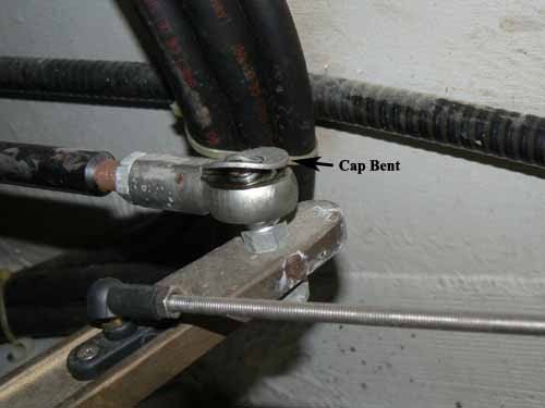
EDIT:* I just looked at those pictures again after copying them and enlarging. It almost looks like those joints are assembled with a non removable stud so as to maintain a parts market for the boatbuilder. It looks like they took*a standard ball joint and inserted a longer stud through the bore so that it extended a few mm above the top of the ball. The stud may have a slight shoulder to hold the washer we see in the first photograph. After the stud and washer are in place, the top of the stud is expanded much the same a rivet head to retain the washer and hold the stud in the ball. This makes the ball and stud a single unit for parts ID and sales purposes.

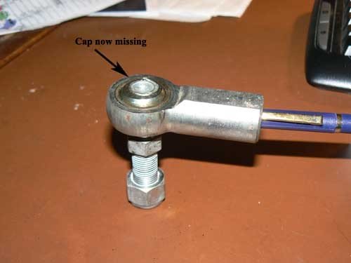
To confirm this, look at the portion of the stud above the nut that rests on the bellcrank or rudder arm. If it is smooth with no threads then it is a stud. Something has happened between the two pictures. The first on shows a washer that someone has tried to pry off with a screwdriver or some other tool. The second picture shows the top of the ball with all the evidence missing. If this is the case, and I now believe it is, then file the top of the broken stud smooth, apply some mousemilk to the area, carefully support the ball and press or punch the stud out of the bore. Replace with a bolt.


-- Edited by RickB on Wednesday 14th of July 2010 02:55:42 PM
 
RickB wrote:

The ball joints under discussion have nothing in common with automotive ball joints. There is no comparison other than the name.
I am very familiar with the construction of the type of ball joint in timjet's photos and for the record, while I cannot speak for every vehicle on the planet, the basic construction is identical to the ball joints I have replaced on my Land Rover, Range Rover, and a few other vehicles I've delt with. The only difference being the automotive joints have different fittings extending down from the ball and socket assembly and there is (usually) a boot to protect the joint from dirt.* But the component concept of the joints-- at least the ones I've changed--- is identical.

*
 
I don't want to get in a pissing match but automotive ball joints are designed to be disassembled. They are pressed in and out of their sockets*plus the ball*is*an extension of its threaded mount.

There is nothing similar between these*devices other than the ball is round. An automotive ball joint on the left, a heim joint on the right.


211452332-M.jpg


-- Edited by RickB on Wednesday 14th of July 2010 03:05:14 PM
 
And the joints on several of the vehicles I've owned look just like your illustration on the right. You know a lot, but you don't know everything
smile.gif
 
Well, I learn something every day.

To tell the truth I am very surprised that an automotive designer would use a heim type ball joint on a car anywhere other than as a lightly loaded tie rod or other application where the load was radial (push - pull) only. They just aren't designed to take an a axial load of the kind that a ball joint sees when used on the suspension.* That is why nearly half the ball is unsupported.

Just for my enlightenment, what kind of car and where were they used?

-- Edited by RickB on Wednesday 14th of July 2010 04:36:38 PM
 
Steering linkages, Morgan, Jaguar (older), Bristol, MG (older) Land Rover (older) and an old Ferrari to name some makes I've worked on back in the day that I recall had the "open" type of ball joint. I've not seen them on any vehicles I've dealt with more recently, probably because of the disadvantages you state.

Because of this experience I assumed the current automotive ball joints like the ones in your left illustration*were basically made the same way.* I did not know that they are designed to be taken apart, for example.* When they loosen up to the point of needing replacement, everyone I've known as well as myself have*simply replaced them with new ones rather than try to*service the old ones.* So I figured you couldn't take them apart.

So I've learned something, too.

-- Edited by Marin on Wednesday 14th of July 2010 05:36:41 PM
 
Gents,

Could we call them "Tie Rod Ends".* Ball joints are the joints that are in the upper and lower end of an "A" Frame and supports the Spindle.* They do not come apart.* When they do the car is at the side of the road with the wheel at a funny angle and sometime a bent fender.

"Ball joints are a part of your vehicle's suspension that connects the steering knuckles to the control arms. A ball joint is essentially a flexible ball and socket that allows the suspension to move and at the same time the wheels to steer. Cars and trucks without strut suspensions typically have four of them (one upper and one lower on each side). Cars and minivans with strut suspensions have only two (one lower ball joint on each side). Some front-wheel drive cars also have ball joints on the rear suspension.
*

Like any other suspension component, ball joints eventually wear and become loose. Excessive play in the joint can affect wheel alignment and tire wear. Loose joints can also cause suspension noise (typically a "clunking" sound when hitting a bump).

WARNING: If a ball joint fails, the suspension can collapse causing a loss of control. So don't put off having a bad set of joints replaced. "

To mix it up a little more.* The Britts called them "Trunnion's".

Just saying.
 
Mmmmm.... no. I'm looking a the shop manual for my 1973 Land Rover and also the parts catalog from Rovers North, the primary supplier of Land Rover and Range Rover parts in the US. They use the terms rather indiscrimately. They call them "tie rod ends" when they are on the ends of the tie rod. They call them "ball joints" when they are on the ends of the drag link. They also call them "ball joints" when they are on the ends of the torque tube that connects the steering box to the steering relay up front. But the hardware itself is all identical. So the definition seems to be up to the person or company doing the defining.
 
Yea but that's Land Rover what do you expect.* They call it a bonnet and wind screen and oh yes they just got away from side curtains 50 years ago.* :>)))
 
True, but then they invented the language. If the Queen calls it a ball joint, the by God, it's a ball joint.
 
That's why it's called English and not American.
Marin as you would know, if it is Pommie built it is built propper, it might not work but it will be well built.
I'm an old MG freak but have been cured ( after an MGA, TF,Magnet ZA and a Midget) and now drive Jap wagons.

Benn
 
Well, we've kind of hijacked Tim's discussion here but since he seems to have decided on a course of action I guess we can get away with it......

I've had a number of British vehicles over the decades and still have two, the Land Rover I bought new in 1973 and the Range Rover. All those years I heard all the stories about the failings of British vehicles, like Lucas "Prince of Darkness" electrical components and whatnot. But my experience, and the experience of the other owners I knew, never matched the stereotype. I've had far more mechanical and electrical issues with our Ford, Toyota, and BMW vehicles than I ever had with the British cars. Almsot everything electrical that's failed on the cars I've owned--- including the Range Rover--- has been German built.

But the thing I like best about British vehicles--- I don't mean today where a BMW looks like a Honda looks like a Ford looks like an Audi looks like a KIA--- is their aesthetics. The most perfect design I have owned is the Austin Healey 3000. Like a dummy, I sold it a long, long time ago when it was just a "used sports car." But Healeys, Morgans, TR-3s, Aston Martins, E-Type coupes, Rileys, MG-TDs, Bristols, fast-back Bentleys, Morris, even the original Mini (the current one is a poor imitation and far too big) and the classic London cab, the list goes on and on, have an aesthetic that appeals to me more than the cars from any other country except a few models of Ferrari and a single model from Studebaker.

So one can deride British cars all they want but in my opinion they knew (and probably still do) how to draw lines with sheet metal better than just about anyone else. I think the best looking new car on the planet right now is the Aston Martin Vantage. I saw a lot of them in Dubai the other month and they are one of the few new cars I've seen that I think looks great from any angle.


-- Edited by Marin on Thursday 15th of July 2010 11:34:58 AM
 

Attachments

  • p1040610.jpg
    p1040610.jpg
    167.4 KB · Views: 65
  • p1040609.jpg
    p1040609.jpg
    204.5 KB · Views: 80
Thanks guys for all your input.

I got home yesterday and had a further look at the tie rod end. The stud does indeed slide up and down within the ball. I had first thought it was pressed into the ball. For that reason the cap does indeed prevent the stud from slipping out of the ball. So the mystery regarding the reason for that cap is solved.

There is no force applied to the cap on that stud. The stud connects the rudder tiller to the tie rod, so only the weight of the tie rod is applied to that cap on the stud. Probably just a couple of ounces, and for that reason the light weight construction of the cap. However, in my view if that cap were to break off completely and the stud slipped out of the ball, Marins' nightmarish scenario could develop.
As Marin states: "And when the ball comes off the top of the stud/bolt you will lose steering control over that rudder, and the tie rod could even drop down into the bilge and jam against something and take away all your steering control."

I also believe the indentation in the cap was put there to break a way the outer portion of the cap if for some reason force was applied to the cap, and thus maintain the integrity of the inner part of the cap which holds the stud in place. I also believe that outer portion of the cap was broken and can be seen raised up in the first photo when an adjustment was made to the tie rod end bolt. I suspect it came that way from the factory, or was adjusted shortly there after.

I can't figure out the thinking involved in the design of that stud and cap. For such an important part, a beefier cap on the stud would seem not only obvious but prudent. Perhaps BP and Toyota are feeling the same way.
 
Back
Top Bottom