Grrrrrr.... 240 or 115v? Flip a coin.

The friendliest place on the web for anyone who enjoys boating.
If you have answers, please help by responding to the unanswered posts.

toocoys

Guru
Joined
Oct 27, 2016
Messages
934
Location
United States
If you're part of CF or the CCCC forgive me, you'll have already seen this.

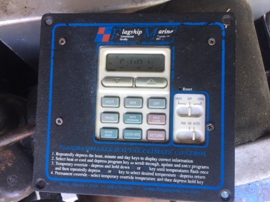
I've been offered a Flagship Marine a/c unit for my boat for a mere $300. It's 16,500btu, manufactured in 2005, and per the tag its a 240v. However, the seller took it from his 29' Bristol sailboat and swore that it ran on 115v 30amp service because he doesn't have 240 on his boat.

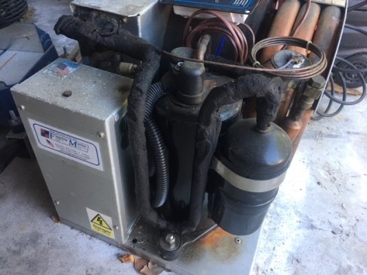
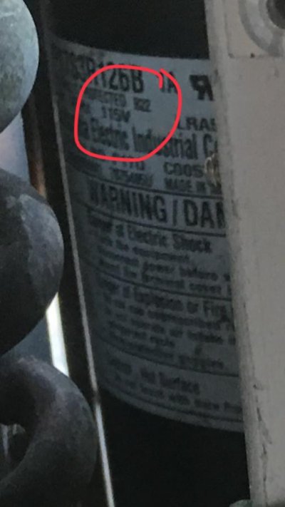
After doing some research, I noticed in the photos that the compressor is labeled 115v. (photos attached). Which means that the compressor was replaced at some point, or that the unit was frankensteined and converted somehow.

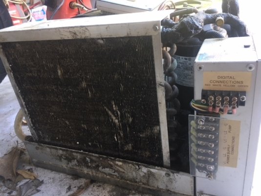
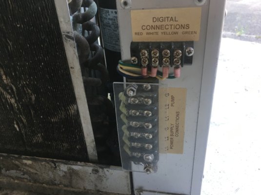
Furthermore, Flagship Marine uses a "heat coil" much like a hair dryer, instead of reverse cycle heating. While the mfg was quite adamant that the unit will not work on 115v, most people say that one leg of the 240 probably powers the A/C while the other leg probably powers the heat coil. I looked in the discharge area and I don't see any coils where they are depicted on Flagships website.

Since we live in Texas, I am the least bit concerned with the heat working as we never need it.

So I'm not sure if this is a good deal, or if this is going to turn out being a big hoorah trying to get it installed. The owner said that he would allow me to install it and make sure it was operational before paying him.

Thoughts? Testing advice? Buehler?
 

Attachments

  • IMG_4575.JPG
    IMG_4575.JPG
    131.4 KB · Views: 92
  • IMG_4576.JPG
    IMG_4576.JPG
    135.2 KB · Views: 91
  • IMG_4577.JPG
    IMG_4577.JPG
    146.9 KB · Views: 105
  • IMG_4579.JPG
    IMG_4579.JPG
    133.8 KB · Views: 96
  • IMG_4581.JPG
    IMG_4581.JPG
    129 KB · Views: 99
  • IMG_4584.jpg
    IMG_4584.jpg
    94.4 KB · Views: 101
  • 3270F58A9CFD478C9AA81B12110D8577.jpeg
    3270F58A9CFD478C9AA81B12110D8577.jpeg
    114.4 KB · Views: 107
  • 67DAA8C5637342FABB9754E263639E6F.jpg
    67DAA8C5637342FABB9754E263639E6F.jpg
    37.9 KB · Views: 95
I think Gaston meant a step up transformer. 240 comes into a boat as 2 x 120.

My dryer is the only 240v application on my boat. I have a 120v 30 amp circuit that goes to a step up transformer. This gives me 240v 15 amp for the dryer.

It is possible that the boat was 125v/50amp and the AC circuit had a step up transformer that the owner was unaware of. It’s also possible some one Frankensteined it.

Can you bench run it from home.
 
What does that mean?

It means Mr. Gaston doesn't know much about electricity.

I have the exact same unit on Delfin, and I'll try to look at the compressor tomorrow to see what voltage it is. I am quite sure it is 240 vac, as that is what it is wired for. Mine doesn't have the heating option that was offered, so I think the advice that one leg of the 240 powers heat and the other the compressor is probably incorrect. Sounds like someone replaced the original compressor with a 115 vac variety, as you suggested.

We don't use a/c much in the Pac NW, so my opinion doesn't mean much, but it has always worked flawlessly when called on. With that limited knowledge, $300 sounds like a screaming good deal.


Awesome! Another friend of mine just pointed something else out as well. 240 would have 2 hot wires, a neutral and a ground for the power supply which means there would be 7 terminals including the 3 for the pump. If you look at the bus bar there are only 6 terminals. Hot/Neutral/Ground for the power supply, and Hot/Neutral/Ground for the pump.
 
Awesome! Another friend of mine just pointed something else out as well. 240 would have 2 hot wires, a neutral and a ground for the power supply which means there would be 7 terminals including the 3 for the pump. If you look at the bus bar there are only 6 terminals. Hot/Neutral/Ground for the power supply, and Hot/Neutral/Ground for the pump.


If I forget to post the voltage on our unit, feel free to PM to remind me. I'll also check on how many connection posts I have, but it sounds like if you supply 115 vac to this unit and it has refrigerant, you should get cooling.
 
Awesome! Another friend of mine just pointed something else out as well. 240 would have 2 hot wires, a neutral and a ground for the power supply which means there would be 7 terminals including the 3 for the pump. If you look at the bus bar there are only 6 terminals. Hot/Neutral/Ground for the power supply, and Hot/Neutral/Ground for the pump.
Close. A 240V (only) load would have two ungrounded (hot) terminals "L1" and "L2", and an equipment grounding terminal "G". No 'neutral'. If the unit was designed for a 120V compressor and other 120V loads with a 240V mains voltage, a grounded (neutral "N") terminal would also be required, like with a clothes dryer in North America.

That unit was designed for single-voltage mains. It's possible the compressor was replaced, and it's also possible the control unit was designed for a range of supply voltage, which keeps things simple when they're built for different parts of the world.

Or so it looks from way over here.

Actually 4 wire 240 vac circuits are preferred now. Used to be 3 wire was most common (and before that 2 wire), but now you have L1, L2, a ground and a neutral. Especially important on boats where the neutral and ground go to different busses, even if they both end up connecting to ship's ground. If you look at the electrical connection photo the OP posted you can see it is a 4 wire setup. I suspect the former owner replaced the compressor and took the 120 off one of the hot legs plus the neutral.

https://www.doityourself.com/forum/electrical-ac-dc/528032-how-wire-240v-generator-plug.html

OP: Do you have the manual for this unit? If not, I can get you a copy of mine.
 
Actually 4 wire 240 vac circuits are preferred now.
4-wire feeder to a 120/240V subpanel, yes. And a boat's electrical distribution panel is essentially a subpanel, as the neutral and equipment ground is connected at the source, not in the boat, assuming no isolation transformer. But only 3 conductors are required for a 240V only branch circuit and load, two of which are current-carrying, like a typical domestic tank water heater or air conditioning condenser (outdoor) unit, plus an equipment ground.

If you look at the electrical connection photo the OP posted you can see it is a 4 wire setup. I suspect the former owner replaced the compressor and took the 120 off one of the hot legs plus the neutral.

That's what I was going off of, but I don't see a neutral connection, only L1, L2, and G for both mains power and the pump. You certainly could take the 120V that way, though the current would double for the same size compressor, and power relays would have to be checked for rating. If I missed it, then I stand corrected, and ignore everything I said before. :blush:
 
Last edited:
4-wire feeder to a 120/240V subpanel, yes. And a boat's electrical distribution panel is essentially a subpanel, as the neutral and equipment ground is connected at the source, not in the boat, assuming no isolation transformer. But only 3 conductors are required for a 240V only branch circuit and load, two of which are current-carrying, like a typical domestic tank water heater or air conditioning condenser (outdoor) unit, plus an equipment ground.


That's what I was going off of, but I don't see a neutral connection, only L1, L2, and G for both mains power and the pump. You certainly could take the 120V that way, though the current would double for the same size compressor, and power relays would have to be checked for rating. If I missed it, then I stand corrected, and ignore everything I said before. :blush:

I was just looking at the photo of the "Digital Connections", which shows red, white, yellow and green connections.

I think the reason for the safety preference on many, but not all, 240 vac appliances is that the ground + neutral provides redundancy for a path to earth that doesn't go through you. This is a pretty good discussion on the topic:

https://www.houzz.com/discussions/2637879/4-wires-for-240v-appliance
 
After sending my photos to Flagship, I received this response this morning:

“Chris after talking to our engineers they said hook it up and run it on a garden hose. Jumper the wires together on the thermostat terminal strip and you should fire right up!”

They confirmed my suspicions and agreed that I most definitely have a converted unit.
 
I do not. The seller only has the unit as it came with the boat he purchased.

I didn't make it out to the boat today, but will try tomorrow. PM me and I'll send you a scan of the manual.
 
Just out of curiosity, why did the US go 115-120v AC, when most of the rest of the world went 230-240v AC..? Albeit with many varying shapes and sizes of plugs. But at least all you need is an adapter plug to run your whatever when travelling, except in the US, and maybe Canada too? - I don't know.
I'll Google it as well, but just interested... :confused:
 
The US didn't go 115-120. It went 110 just like the rest of the world. After WWII most the world felt that 220 was a better choice. The problem was that most Americans had lots of expensive Electrical applicance that were 110, the rest of the world didn't own all these expensive electrical appliances so it wasn't a hard ship to switch to 220, only the rich were affected. In the 1950's everyone decided that more was better and the US jumped to 120 while the rest of the world jumped to 240.


In other words, some times its a disadvantage to be the first guy on the street with something new. Now the real question is why is everyone still using 50hz when 60hz is superior?
 
"Now the real question is why is everyone still using 50hz when 60hz is superior?"


The same reason "smart plugs" never caught on , the installed base is VAST!
 
Just imagine being in Japan. Half the country 50Hz, other half 60Hz. Uggghh.
 
Just imagine being in Japan. Half the country 50Hz, other half 60Hz. Uggghh.
And 100V nominal for single-phase. An odd voltage by world standards.


Another oddity is (some) job sites in the UK, where 110V hand tool voltage is required for safety even though their nominal single-phase voltage is 230V, and it's created via a center-tapped isolation transformer so the voltage to earth is no more than 55V for single-phase, and 63V for three-phase 110V systems. Similar to our 120/240V, center-tapped and grounded system where voltage to ground is no more than 120V, they use two hot leads at 55V with no neutral (since there's no need for 55V power), and the equipment grounds are bonded to the center tap.
 
Last edited:
Is Euro power (220v) like our 240v in the sense that each leg is only half the voltage compared to earth (center tapped)? So you can't get "bit" by more than 120v unless you go across two hots?
 
Just out of curiosity, why did the US go 115-120v AC, when most of the rest of the world went 230-240v AC..? Albeit with many varying shapes and sizes of plugs. But at least all you need is an adapter plug to run your whatever when travelling, except in the US, and maybe Canada too? - I don't know.
I'll Google it as well, but just interested... :confused:

Part of it was leading in electrification and making a pioneer's mistake. As I understand it, 120 vac was thought by consumers to be safer than 240, which it sort of is under many circumstances. Better than the alternative being pushed by Edison, which was DC current. DC fans used the danger of ac as their primary argument for not making ac the standard. Good thing they lost, since we would have run out of copper a long time ago if DC was used for household current.
 
Last edited:
Is Euro power (220v) like our 240v in the sense that each leg is only half the voltage compared to earth (center tapped)? So you can't get "bit" by more than 120v unless you go across two hots?

No, it's a single 240 hot and a neutral. Watched my infant son drop a key down between the outlet and plug at our house in Australia. Let it go just before it shorted out, or he may well have been killed. The whole drama played out in about 1 second between when I glanced up and when the flash happened.
 
60 “better” than 50Hz??

Hmmm. On transmission cable skin depth is at play. Less current density drop with 50Hz.
60Hz can produce less light flicker and marginally lighter transformers.
 
I worked on a big machine design project in the US with a couple of Brits, one of whom made fun of our wimpy 120V single-phase power, when I reminded him of job site reduced voltage requirements in the UK. :facepalm: And we still have 240V for large loads. No need for higher voltage for a table lamp, after all.

Another oddity in UK power is the so-called Ring Circuit (which I know by the obsolete term Ring Main), in which both ends of the branch circuit are connected to the 32A breaker (or 30A fuse), neutral bar, and earthing bus. The 2.5mm^2 [14 gauge] wiring is too small for 32A, but since it's fed from both ends, it's allowed (still allowed for new work in their codes, too).

Problem comes in when continuity is lost on one end or somewhere in the ring, where you can end up overloading a conductor, potentially by a lot, and you might not even know it since the ciruit still works.

Of course, we have our own oddities in the form of the multi-wire branch circuit (MWBC), where a single neutral is shared between two hots of opposite 'polarity'. Lose the neutral connection and you lose the zero volt reference at the load, so the actual voltage across the load can wander depending on what's connected on each leg, potentially burning things out from overvoltage, or going dim (incandescents) or burning out (induction motors, from overcurrent).

And then there's the risk of someone moving one of the two hots to the same pole as the other, usually with half-height breakers thinking they're the same thing as two full-sized side by side breakers (it's not), potentially putting double the current on the neutral rather than only the difference. And that happens, too.

And in the case of obsolete but ubiquitous ungrounded 3-wire dryer and range connections, with the frame bonded to the neutral, the frame will become energized, which happens (been zapped twice myself, and I'm not even a sparky). Which is why they've been disallowed since '96 for new work.

Hopefully this isn't a breach of protocol, babbling on about electrical oddities, but the OP got his problem solved, so I'm hoping not.
 
Last edited:
"Another oddity in UK power is the so-called Ring Circuit"

These are seen in some aircraft to help absorb battle damage,

was tried on boats that have remote operation options for individual circuits.
 

Latest posts

Back
Top Bottom