Let's design a dingy crane?

The friendliest place on the web for anyone who enjoys boating.
If you have answers, please help by responding to the unanswered posts.

MVCalypso

Veteran Member
Joined
Jun 13, 2010
Messages
48
Vessel Name
Calypso
Vessel Make
Island Gypsy 36 Europa 1984
Hi,
For a few months now, I've been noodling about a dingy crane design project.

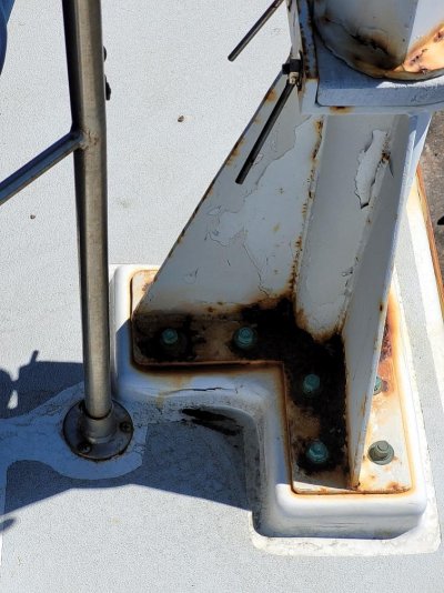
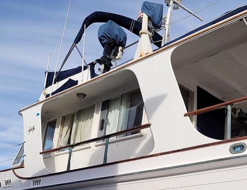
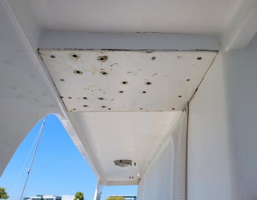
In December '22 I had to remove the dink crane from my boat as its mount started leaking into the saloon. That potential problem was averted. But not being able to carry or use the dink has become an annoyance. So I think I need to figure out a replacement.

No commercial products have held my interest yet (different reasons for diff products). So I'm leaning toward a custom design. Before I go further down the road that (currently) seems best, I'd like to tap into the group's experiences.

Attached is a intro write up of how I got to this point, what problems I'd like to solve, and what I've considered so far. This is a real world engineering problem; the functional desires are not trivial, the budget is not unlimited, and of course I'd now like to have it done yesterday. :rolleyes:

I'll trade project time off for the other two - doing much of this DIY is part of the fun of the project to me.

If you're the type who likes to do arm chair design, I'd like to hear your inputs / commentary. Frankly, I'd love to hear "Did you consider ABC?", so I could respond with "Heck, no I didn't, that's a fabulous idea!".

Any takers?
 

Attachments

  • Calypso Crane sketches r6 July 2023.pdf
    274.9 KB · Views: 202
A few observations:

By lengthening the boom, you have created substantially more leverage on the base.

Your weight calculation don't include shock loading, only dead weight. Other than absolutely flat calm water, when the boat rolls slightly, you start to create shock loading as the dinghy reaches its lowest point and then is pulled up. Even another boat going by with a modest stern wave (not a wake) will create some roll on your boat and thus some shock loading.

Going back to the original point of increased leverage, I'm doubtful that your 40 year old boat has the same roof structural strength it had when new. While it might hold all the weight in that one area, I'm not sure it will handle the increased leverage.

Ted
 
I don't see your location on your post. If you are in range of Tacoma I have a good alum welder I can recommend.
 
O C Diver has brought up several good points. The basic design approach should be as follows:
1. determine your dimensional requirements
2. determine your nominal load requirements
3. apply necessary safety factors - impact, roll, pitch, yaw, etc.
4. design davit accordingly (ideally find a readily available market design, https://www.northerntool.com/categories/jib-cranes)
5. design necessary mounting plate (see all of the above)
6. determine mounting surface requirements and existing suitability


These are the basic starting points for a jib crane design. Remember, if your safety factor is one at any point of the design, that is failure.
 
I don't see your location on your post. If you are in range of Tacoma I have a good alum welder I can recommend.


Thanks for the offer. I'm in the San Francisco bay area. I know of a couple of folks in the area, but they're production oriented vs one-off projects.
 
Your folding crane idea is not bad as long as you need that much flexibility, but do you?
However, these considerations come to mind:

1. The original mast-less crane was adequate to lift the dinghy, without a mast...

2. Your goals seem to be higher lift and longer reach, and not a great deal more.

3. I would replicate the original proven design with those modifications and focus
your efforts on improving the salon roof so it can support the added forces. ;)
 
Last edited:
Have you looked at the Nick Jackson pipe davit cranes? It's 2-pieces with the stationary piece well supported and sealed. The rotating piece fits into the stationary piece in a manner that sheds water. It's a simple design. I paid about $2k for one shipped to SF Bay 4-years ago.

Pipe Davits

Peter
 
As others have mentioned, it looks like mounting that way would be a poor choice. Even if it held for a while, it will weaken the structure with the repetitive loading and flexing of the deck. Leaks will inevitably follow.
I also believe that powered rotation of the boom, or at the very least, a way to control the speed of the rotation is a must have feature. When the loaded boom swings out, the boat will list and the swing can quickly get out of hand.
I would try to look for a new mounting position where you could mount a through deck style of crane. I know the pipe running through the cockpit is a space taker, but the added strength of that style crane is worth it, especially if you go to a bigger tender someday.
 
A few observations:

By lengthening the boom, you have created substantially more leverage on the base.

Your weight calculation don't include shock loading, only dead weight. Other than absolutely flat calm water, when the boat rolls slightly, you start to create shock loading as the dinghy reaches its lowest point and then is pulled up. Even another boat going by with a modest stern wave (not a wake) will create some roll on your boat and thus some shock loading.

Going back to the original point of increased leverage, I'm doubtful that your 40 year old boat has the same roof structural strength it had when new. While it might hold all the weight in that one area, I'm not sure it will handle the increased leverage.

Ted

You've raised a couple of good points that I'm still working on.

1) Moments from boom length
The increase in boom length does change the moment arms involved. So does launching the dink assembled (vs dink, then OD etc) as the weight is lifted all at once.

The current dink is about 160lb assembled. I swagged a design weight of 500 lbs (static, for safety factor and would like 1000 as the target (not needed or any dink that would fit my boat, just for more calc pad). I figured it would depend somewhat on what the pipe strength would need to be.

More years that I care to admit, I could have done the engr calcs - but that was 45+ years ago. I was a EE and Comp Sci guy by profession. The ME stuff has faded from my brain over the years.

Because of that, I engaged a well respected local Naval Architect to do some prelim calcs for me. The answer came back that this is doable with sched 40 6061 pipe at the 500 lb target. Assuming appropriate fab work, the sched 40 crane starts bending at somewhere around 1400 lbs (static load).

So for a first pass, I think this is in the the right ball park. But...

2) shock loads
This is the one that I'm clueless on, and I have no idea how to even swag it. What is a reasonable multiplier from static to an impulse load? I don't know. I sort of suspect it could be come a delta epsilon game - someone picks a factor and then we invent a scenario that exceeds it.

This is a topic where I think I'll need to pay more $$ to a pro to get an answer I feel comfortable trusting.

Fortunately in this situation , the weight of the crane is not crucial (new one is Al, old one was steel) so I could go with heaver/stronger matl if needed.

I think the crane itself can be made plenty strong.

3) Crane mounting -
I want to use the old crane mount location / approach. Partly because it's a real hassle to move the mount location and partly because it's in a strong location and it's well supported. See pic.

I've attached a pic of the old (rusted) crane mounting base for reference.

The old crane was a steel, welded, Tee that bolted thru a Block on the FB (to get the crane vertical as the FB deck has a slope), thru the FB overhand structure and then thru a large (about 18" x 14" and 1/4" thick) SS backing plate on the bottom of the FB structure.

The block shown was cut off and the area glasses to stop the leak that showed up last winter (it failed the "resistant to atmospheric rivers test from mother nature). The top block was soft, so a new one will need to be made - perhaps from FRP instead of wood - TBD.

The location of the base is such that it is supported inboard by the cabin wall and outboard by the "upright" panel that supports the FB overhangs. So it is at the top of a strong inverted "U" structure.

The FB deck in this area is solid. Most of the FB deck is foam core, the mount base foam core was replaced with hard wood - looks to be real mahogany- not positive re wood species). In any case it's solid and shows no rot.

This is overall, a 4"+ thick, solid hardwood and FRP composite structure. With the load spread to the upright "walls" via the SS backing plate. I think it's strong - but I can't quantify that (without some rather undesirable destructive testing). This is where the Engr in me struggles with the my inner shade tree mechanic. To do the strength testing needed to get a real answer just doesn't seem practical.

The water followed a couple of bolts, ate the upper block then followed the crane wire into the Saloon. Stopped that before it could impact the finish on the interior teak wall panels.


I get the concerns. I share them. I just don't know how to resolve them into quantifiable values that one can do the engineering with.

I'm all ears for any pointers on how to be more formal about this.
 

Attachments

  • old crane base.jpg
    old crane base.jpg
    145.7 KB · Views: 22
  • Crane support location.jpg
    Crane support location.jpg
    33.9 KB · Views: 22
Your folding crane idea is not bad as long as you need that much flexibility, but do you?
However, these considerations come to mind:

1. The original mast-less crane was adequate to lift the dinghy, without a mast...

2. Your goals seem to be higher lift and longer reach, and not a great deal more.

3. I would replicate the original proven design with those modifications and focus
your efforts on improving the salon roof so it can support the added forces. ;)


Yep, that's basically how I go to today's ideas. The lift increase is to make clearing the lifelines easier. The longer reach is to get the lift point to where the dink will balance.


Please also see the notes I posted to OC Diver - it has more info re crane base mounting.
 
Have you looked at the Nick Jackson pipe davit cranes? It's 2-pieces with the stationary piece well supported and sealed. The rotating piece fits into the stationary piece in a manner that sheds water. It's a simple design. I paid about $2k for one shipped to SF Bay 4-years ago.

Pipe Davits

Peter


Thanks for the reference. I've looked at a lot of cranes over the past year, but I'll go look at this one too.
 
Whoops, forgot to mention: The naval architect I hired spent a afternoon with me looking at the existing structure so he had some idea of the mounting arrangement too.
 
Thanks for the reference. I've looked at a lot of cranes over the past year, but I'll go look at this one too.
Well, the second picture you posted shows a thru-deck pipe davit would almost certainly obstruct side deck access. Somehow, the load must be carried to the deck below. I guess you could fabricate a very heavy C-shaped bracket where the top is a backing plate, runs down inside of roof support, then fastens to the side deck. Gussets would be your friend.

It's hard to get a feel from pictures, but I'd consider finding an off-shelf davit, place it where it should be, then spend part of the money you would spend on a custom davit to repair the fiberglass. You'll have money left over, and a better davit. I think if you look closely at davits such as the Nick Jackson one I linked, even in a simple pipe davit you'll see there's a fair amount of engineering and design in them. The nose piece with sheave, delrin bushings, winch base, strong back, etc. All surmountable.....a cost of time and money.

Good luck.

Peter
 
Last edited:
As others have mentioned, it looks like mounting that way would be a poor choice. Even if it held for a while, it will weaken the structure with the repetitive loading and flexing of the deck. Leaks will inevitably follow.
I also believe that powered rotation of the boom, or at the very least, a way to control the speed of the rotation is a must have feature. When the loaded boom swings out, the boat will list and the swing can quickly get out of hand.
I would try to look for a new mounting position where you could mount a through deck style of crane. I know the pipe running through the cockpit is a space taker, but the added strength of that style crane is worth it, especially if you go to a bigger tender someday.

Some good observations here -

Please see the post to OC Diver also - does any of that info make you feel more or less comfortable with the mounting?

---
The rotation point is important. The old crane is is basically two pipes, the lower on is part of the base, the upper one rotates in the lower pipe. I should have mentioned that the rotation is not free swinging. Sorry about that.

There is a U bolt friction device at the top of the old crane base. It applies friction to the inner pipe and can control the "ease of swing". The U bolt clamps a shoe against the inner pipe and the U bolt ends are threaded and have screw handles to apply pressure. I've not found this to be an issue over the years, so I think duplicating the approach will work for me.

The U bolt also acts as a locking mechanism to secure the boom when not in use. I intend to back that up with a deck pad eye for the lifting halyard.

---
Re a standpipe to support the crane... I get the advantages. I just have not been able to bring myself to trade off the aft deck space it requires. IT would really interfere with lots of things (side deck transit, line handling, laz access etc.). Just doesn't feel liek the right trade off to me (yet) - but if the new crane tears out the FB deck, well... :eek:
 
Here's a picture of my Nick Jackson davit crane. I mounted in aft quarter. Nothing magic here. I had a sizeable mast and boom which I decided to get rid of so I could make a larger hard top, plus when I eventually make it to the east coast, bridge clearance is facilitated.

Will be interested to see what you end up doing.

Peter Screenshot_20230722_125535_Photos.jpg
 
It's hard to get a feel from pictures, but I'd consider finding an off-shelf davit, place it where it should be, then spend part of the money you would spend on a custom davit to repair the fiberglass. You'll have money left over, and a better davit.

I have a basic question about pipe davits:
Since the pipe davit has a fixed radial distance between the davit pivot point and the lifting halyard, that seems to mean that either you place the pipe davit and that determines where the dink has to go (so you can pick it up where it balances) or you locate the dink on deck and that determines where you have to mount the pipe davit.

Is there some other degree of freedom that I'm not seeing here?
 
Yep, that's basically how I go to today's ideas. The lift increase is to make clearing the lifelines easier. The longer reach is to get the lift point to where the dink will balance.

Please also see the notes I posted to OC Diver - it has more info re crane base mounting.
So you are really talking about inches, perhaps a foot higher and a foot longer?
I would resist the temptation to over design/engineer and keep it sorta simple. ;)

I am a fan of rectangular-section aluminum tubing in these situations (or an H-beam).
Something around 3"x6"x0.25" wall thickness may suffice as a starting point.
It offers ease of fabrication and mounting possibilities with little if any welding needed.
The strength to weight ratio can equal or exceed that of round section tubing as well.
 
Last edited:
I have a basic question about pipe davits:
Since the pipe davit has a fixed radial distance between the davit pivot point and the lifting halyard, that seems to mean that either you place the pipe davit and that determines where the dink has to go (so you can pick it up where it balances) or you locate the dink on deck and that determines where you have to mount the pipe davit.

Is there some other degree of freedom that I'm not seeing here?
My pipe davit came long so I had to cut down the boom by a foot or so. But yes, the radius is fixed with a simple pipe davit. There are davits with arms that go in and out, but you start talking serious money.

Peter
 
Well, the second picture you posted shows a thru-deck pipe davit would almost certainly obstruct side deck access. Somehow, the load must be carried to the deck below. I guess you could fabricate a very heavy C-shaped bracket where the top is a backing plate, runs down inside of roof support, then fastens to the side deck. Gussets would be your friend.

It's hard to get a feel from pictures, but I'd consider finding an off-shelf davit, place it where it should be, then spend part of the money you would spend on a custom davit to repair the fiberglass. You'll have money left over, and a better davit. I think if you look closely at davits such as the Nick Jackson one I linked, even in a simple pipe davit you'll see there's a fair amount of engineering and design in them. The nose piece with sheave, delrin bushings, winch base, strong back, etc. All surmountable.....a cost of time and money.

Good luck.

Peter

I agree with Peter.

Speaking from the P.O.V. more of a "shade tree mechanic" than a real mechanical engineer, I have experience with this issue. I have a Nick Jackson Tube frame that came mounted on my Cheoy Lee Pilothouse 34 Trawler. I bought it that way three years ago. I made a bad choice in acquiring a TOO BIG and TOO Heavy center console type 5 passenger dinghy. A Novurania (13.5 ft long with 40 HP 2 stroke Yamaha ob), probably 1250-1350 lbs. and broke my aluminum pipe davit.

Mine is mounted to the lower side deck and gains strength from the bracket at the boat deck level. I had it rebuilt by adding an addition 3/8" thick aluminum pipe that had an I.D. matching the original O.D. of the pipe. I believe the original was schedule 40 and had an internal flitch plate styled stiffener. When over skinning the original pipe we drilled many more holes to attach both the inner pipe and new 3/8" thick outer pipe to the 1/4" aluminum bar stock stiffener.

Now we have a cheap ATV winch rated for 2,000 lbs pull strength and dyneema line to lift the lighter AB aluminum hulled RIB and a 6 hp Tohatsu ob.
plus fuel tank and gear. It does lift fine and we have no problem single handing the rig up and down as needed. I did mount a separate battery box with 2 group 31 batteries, one is used, the other for back up as a spare. I routinely connect a battery charger to them to keep them charged since the solar panel I mounted atop the battery box failed in under a year.

It does require me to use my thigh to push the dinghy, while suspended toward the center line chocks. I find the pick point doesn't have to be directly over the item being picked or placed, just within 12-24 inches. Meaning I can use it to hoist just the ob to place on a rail mounted cradle some 3 feet away from the pick point. It just keeps the weight on the pipe davit while I manipulate it to its resting place and vice versa.

Well, that is simpleton's approach for what works for now, at least up to the desired 1,000 lbs. My 2 cents are just schedule 40 will NOT cut it, even with an internal stiffener. Also, I trust the lower mounted through boat deck design much more than I would had it been surface mounted to upper deck as your original steel unit was. Just don't want to add those forces to even a solid boat deck. My side decks are narrow, just 15-16" wide so having it through bolted with backing plate to an angled deck space that is already narrow and close to the vertical doghouse structure makes me believe it is in a much stronger location.

I hope this helps or at least causes some good conversation to happen.
 
Here's a bottom view pic of the mount area. The block which is glassed in is mahogany and spreads the downward load into the uprights on either side of the plate. The open hols are the 1/2" bronze bolts that went from the bottom up thru the assembly and thru the old crane base plate. The bottom of the bolts are oval head and sit nicely against the plate. The top of the bolts are threaded and nuts held the crane base down.
 

Attachments

  • Crane base bottom view.jpg
    Crane base bottom view.jpg
    35.1 KB · Views: 22
Now that last photo makes me much more confident in a boat deck level mount.

Just letting you know schedule 40 x 3" O.D. with a 1/4" stiffener welded internally wasn't enough to reach 1,000 lbs. Adding 3/8" thick over the schedule 40 and drilling holes every six inches to weld stitch the inner stiffener on both edges to the schedule 40 and the 3/8" outer tube made it work. Of course we seam welded the two tubes at base and did a tapered cut and welded at the top as well. I could have done a neater job enlarging the bracket that holds mine to the doghouse/salon wall, but I kept the original base. Added High Density Poly Ethylene (HDPE) as a friction plate to aid the swivel feature and it is easily controlled manually. No real worries of runaway on the 180 degree swivel. Just wouldn't do it in anything other than fairly calm wind/water scenario.

I can send photos if that helps.

DJ
 
Last edited:
And that 3/8" thick x 3.75" O.D. pipe and the drilling and welding cost me $700 three years ago, so I thought the price was fair. They do make them rated for up to 1,000 lbs. but mine wasn't up to the task. It lifted the Novurania out of the water and snapped. Got a BIG fishing boat to place it up there and had no problem lowering it one time and saw the flex and decided a stronger pipe davit and a lighter dinghy was the answer to easy single-handed deployment and retrieval of the 10.5 ft AB aluminum RIB with smaller outboard. That Novurania is a beast and with its fiberglass hull and internal fuel tank, batteries and equipment had to be close to 1,300 lbs. or more. I didn't want to remove it and try beefing it up another time. The flex was scary.
 
Last edited:
We installed a St Croix Junior removable manual crane on an IG36 Europa now sold. Roughly in the same position over the aft overhang support and the aft cabin bulkhead. We fitted an ss plate under the top plate and bolted through. The plate had a right angle section incorporated which was screwed to the port side of the cabin.
Designed by an engineer on our marina, it was to lift a 2.6M non rib inflatable, without motor, weight around 30kg.
Deflection under load persuaded me to fix a line when in use to support the crane vertical shaft back to the mast.
There was enough length on the crane "jib" to lift the dinghy from a centered ring with 3 or 4 attachment snap shackles to the dinghy which needed adjustment to it balance it nicely
Retrieved, the dinghy sat on the aft section of the FB.
We didn`t use it much, mainly due to the loading and fiddling about. The St. Croix crane was a smart well made piece of equipment.
 
Here's a bottom view pic of the mount area. The block which is glassed in is mahogany and spreads the downward load into the uprights on either side of the plate. The open hols are the 1/2" bronze bolts that went from the bottom up thru the assembly and thru the old crane base plate. The bottom of the bolts are oval head and sit nicely against the plate. The top of the bolts are threaded and nuts held the crane base down.

In my unschooled opinion, you need to carry the load downward, which will increase leverage arm. See attached sketch - a 3/16" SS backing plate with vertical bracket and gussets to minimize flex and working of material. Won't be cheap., especially if davit crane is custom. You could easily add $2.5k (or more) in costs which will add $0 to the overall value of your boat if that's a consideration (a boat like this is expected to have a dink and retrieval sytem).

Peter

GB36 Dinghy Crane Backing Plate.jpg

EDIT - I think the above is similar to what BruceK describes.....

We fitted an ss plate under the top plate and bolted through. The plate had a right angle section incorporated which was screwed to the port side of the cabin.....
 
Last edited:
Good grief, MVCalypso is only lifting the same lightweight inflatable he already has,
and adding another 100 or so pounds of leverage. Stop spending his money!
 
Good grief, MVCalypso is only lifting the same lightweight inflatable he already has,
and adding another 100 or so pounds of leverage. Stop spending his money!
The one that resulted in leaks into the saloon (Post #1)?
 
The one that resulted in leaks into the saloon (Post #1)?
Leaks, which could happen with a 5000 lb crane and MVCalypso reports no structural issue?

If I spent more than $1-1.5k on the entire project that would be too much,
but I can design, fabricate, weld, wire and engineer, etc.
 
Last edited:
Dear OP,
Retired ME here, so I know/remember enough to be dangerous! Designed a few jib cranes back in the day, a couple for the military, two got patented, I think.

They typically referenced existing code for land/dock cranes, with stuff thrown in for their own unique interests.

Key for me was we primarily designed to deflection limits, then checked stresses/moments in various places. An "easy" classification would be L/150 to L/225, L being the length of the cantilevered jib. More complicated constructions or applications could drive that to L/400. Suggest you take a look at deflection of any proposed design at rated load.

Looking at your situation your "L" is the base + rotating standpipe + complicated by the existing mounting pad built into the upper deck, that is where you see a large moment under load, as you know. The bending load on that is imposed by the boom wire at about 30 deg angle, that increases bending load.

I have a hard time estimating the stiffness of that area, but feel it must somehow be made to take more moment loading, its a twisting load on a sandwich plate structure with tie-in to the rest of the boat hard to estimate. Something like what MV suggested in post #25, but know that plates are bad in bending/twist without reinforcement.

The codes told me to design to deflection limits, so that's what I did. Suggest you ask the jib crane guys suggested up thread if they design to deflection limits and/or bending moments, likely you'll learn something there.

Good luck! It'll all work out!
 
In my unschooled opinion, you need to carry the load downward, which will increase leverage arm. See attached sketch - a 3/16" SS backing plate with vertical bracket and gussets to minimize flex and working of material. Won't be cheap., especially if davit crane is custom. You could easily add $2.5k (or more) in costs which will add $0 to the overall value of your boat if that's a consideration (a boat like this is expected to have a dink and retrieval sytem).

Peter

View attachment 140887

EDIT - I think the above is similar to what BruceK describes.....

You’re close with this idea Peter, but the vertical section should be a hat shape. Or a rectangle tube or channel welded to the upright plate. Move the gusset out enough to cover 3/4 of the horizontal plate. Try to maintain a 3:1 ratio of height to length on the gusset(s) if there’s headroom. Or give them a nice radius shape so they don’t look so industrial.
For those that think this is overkill, I do remember some discussion of upgrading the tender at some point. Better to plan for it now than do it again when a good looking rib comes along.
 
Back
Top Bottom