Fuel System Redesign

The friendliest place on the web for anyone who enjoys boating.
If you have answers, please help by responding to the unanswered posts.

bridaus

Senior Member
Joined
Jun 10, 2017
Messages
240
Location
USA
Vessel Name
Morgan le Fay
Vessel Make
KK 42
Embarked this morning on a bit of a flight of fancy...

My KK42 is at a new marina as of Tuesday of this week, that is another story in another thread... that I need to update.

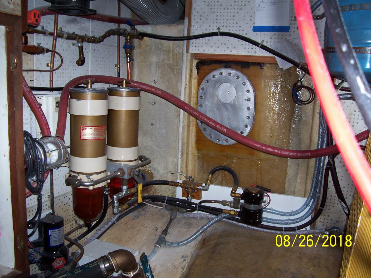
This morning, I decided to layout a new fuel system, that I've been thinking about, since the original system in her now is suspect (no issues, just old and failed once on PO already). This is a project that I probably wouldn't start until April at the earliest.

Goals (some conflict with others as expected, therefore compromises will have to be made).

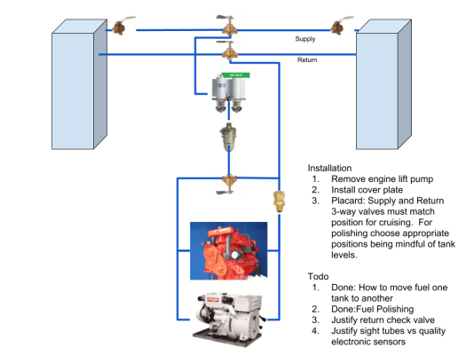
  1. Simplicity: Less stuff is less to break. I want the minimum components that would provide safe and reliable delivery.
  2. Electric priming. To me should have been standard equipment. The trouble everyone has bleeding these dang things, and for a few hundred bucks that can go away. And provide safety as well? Seems a no brainer to me. Plus, swapping in a spare is easy.
  3. Ability to move fuel from one tank to another: I consider this a safety and convenience feature. Adjust trim, polish a tank, move all bad fuel to one tank, etc. The boat has 7-800 gallon capacity, and will be coastal cruising for the next 5-10 years, and then maybe offshore after that.
  4. Fuel Polishing: In the design, it should be able to polish. Not a massive polishing system, but one that with regular use could get the worst out, and not require drilling more holes with more valves in tanks that could fail.

Possible controversial design ideas and related questions:

  1. No sight tubes (or should I?). If I'm offshore, and the electronic sensors fail, for one I should have already done the math to assure we'd make it with reserves, and with some rechecking of math and even running a tank to nothing I have electric prime to move to the other tank and continue.
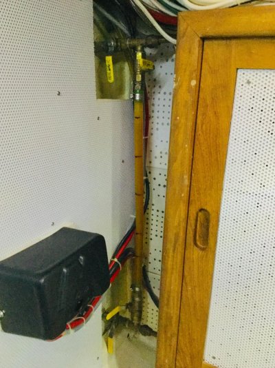
  2. Inspection Plates: Could I replace them with plexiglass (fuel resistant?)? Backup fuel level for removing sight tubes.
  3. Remove on engine lift pump: Engine driven lift pumps have a small but real risk of breaking in a way that could strand you. With electric pump and spare plus four different spare battery sets I see this as an obvious choice for reliability.
  4. No shutoff valves at tank for returns. I'm not sure why they are needed, but I'm probably being an idiot here and someone will point out my errors.
  5. Do I need the check valve in the return line before the polishing system dumps fuel in the line? My feeling is that I don't want to accidentally push fuel backwards into the injection pump (not sure it can or not...).

Please feel free to point out the errors of my ways, there may be many. I may have forgotten an entire concept. It's just a flight of fancy for now, as there are a lot of other things I have to do first before I even touch the fuel system.
 

Attachments

  • KK42 Fuel System (4).png
    KK42 Fuel System (4).png
    163.3 KB · Views: 255
Last edited:
Only comments I will make is one reason that many folk have for keeping a mechanical fuel pump is if the electrical system fails then the electric fuel pumps will also fail.
With an all mechanical system if you can get fuel to the engine and get the engine started, it will run. THat also goes for the shutdown or fuel cut off valve. If power is needed to run that is also seen as a big disadvantage.

The electric priming pumps - sure.
 
Well, if you're looking for opinions:

Not a fan of shared fuel source for generator and engine.
Electric fuel pumps fail also. If you want to improve reliability, treat it as a raw water pump with time scheduled maintenance or replacement as opposed to waiting for it to fail.
If you want simplicity and reliability, draw fuel for engine and generator from the one same tank with only a fuel shutoff valves. Set up a simple transfer / polishing system that allows you to draw from either tank and return either tank. If you keep the suction manifold low, you could equalize the tanks with gravity siphon effect if your pump failed.

Ted
 
I’d keep the sight tubes. You can’t have a more reliable level indicator. Just have ball valves so you can shut them off at the tank. Why replace the inspection ports? Are your tanks fiberglass or steel?
 
I believe they are fiberglass.

Replace inspection ports with see through material just for the added ability to peer inside and gauge levels from 40-60% or maybe even wider.

Remove sight tubes because even though they are reliable, they are redundant, add valves, and in theory are a possible diesel bilge fill hazard. I want super simple.
 
Good point, batteries do run down. Fuel pump would keep going. Maybe it stays.
 
Nothing unreliable about sight tubes. Just leave them valved out unless checking level.
 
If it matters, I have to replace my sight tubes. There is a distinct lack of being able to see through them. That annoyance might be coloring my view of them. :)
 
I just modified my fuel system.

Added a Webasco electrical fuel pump to the Generator Racor 500 circuit.

Fuel is supplied via the existing Grand Banks fuel manifold. The polishing pump was put inline before the WAY oversized generator Raycor 500.

Simple 1/4 mini valves from NAPA allow me to isolate the polishing circuit, and return fuel to either tank or back to the manifold.

With existing tank and manifolds I can do about anything. Polish while underway, with genset running, etc.

I expect it to move at least 30gph. I have an isolated squeeze ball circuit on each filter to prime filters.

It is all hard plumbed, is simple to understand, and can be reconfigured in the boonies to do anything, including emptying the tanks to drums.
 
Do a magnet test on the tanks, they may be coated. See thru inspection ports on fuel tanks might not be legal, your surveyor can probable tell you. I’m also a fan of sight glasses with shut off valves.
 
Change out your mechanical lift pump on PM basis as suggested by OC, Clectric etc. I changed out one and after 13 years it was doing fine, but just time. Sure, if you want put in an electric but valve it such that it is ready to go if needed but off line most of time.

My wire braided “clear” sight tubes remain viewable after 14 years. BTW, lots of ways to hook up a “polishing” system. Suggest you keep your primary fuel delivery system as simple as possible and start out with newly cleaned tanks. Maybe a “polishing” system would then be the proverbial solution for a problem that doesn’t exist.
 
Fuel system

Bridaus, -- does that mean you name is Brian ?

Glad to meet a fellow KK-42 owner & also I understand your a pilot - well so am I. We pilots, often think alike, as pilots, we like back up systems & to keep things simple. So I understand some of your thought process.

First - your diagram even though I understand it is a rough sketch, does not reflect the true KK-42 fuel system design. The supply lines come off the bottom of the fuel tanks (not the top as you show) as a gravity feed to the mechanical fuel pump, as I recall, unless you have replacement tanks that are not OE, & it was changed.

Next - any fuel polishing system you add needs to NOT impact the main fuel feed system at all. - it needs to be completely separate.

YES - Adding a fuel primer circuit is a good idea, but must be designed & set up properly or can cause issues & it can also work, if designed properly, to be a good back up to your mechanical fuel pump should the need arise. See my priming system in picture below.

Adding a clear fuel window at your clean out access port is Not a good idea - the more light that gets in there the more algae growth there will be. Also not Coast Guard legal, so not a good idea & not particularly useful as where you need to see is down at the very bottom of the tank, so half way up the sides is not useful for your perceived fuel inspection of what the fuel looks like, mid tank fuel clarity is not what you need to know. So it does not give you the information you think it would.

I have now been told by "SEALIFE" that to the best of his knowledge all KK-42's through hull #65 have solid drop in 1/2" thick fiberglass tanks. No steel at all till after Hull # 65. This is great news for the earlier models !

In the KK-42 Blueprints it says, in error, that the tanks are 400 gal each, for 800 gal total. I have confirmed with KK in Stuart , Fl. & Also myself personally that is an error / oversight, as we have an 1982 KK-42 # 35 & drained our tanks 100% that the OE tank factory feeds would permit to flow fuel & refilled them while measuring what it took to refill them & they have an OE tank actual capacity of just couple gallons over 350 gal each, which turned out to be a usable fuel capacity of just a few gallons over 700 gal. total, usable fuel. :banghead: -- so capacity of OE fuel tanks is 700 US Gallons.

Yes, there was a little fuel still left in the tanks, but it is not usable fuel & your sucking air & your engine would die of fuel starvation. We did not measure how much that was, but since it is unusable, & this extra fuel weight was not critical on a boat like it is in aircraft & the engine would suck air & stall, we felt it was a moot point. If you're a pilot & you have flown Piper Aircraft, you should be very familiar with usable fuel & unusable fuel & that they are different numbers, compared to total fuel weight on board & unusable fuel is included in the base weight of the aircraft or vessel. -- So 700 Gallons is your fuel capacity.

Next question - (if you have one, many do) -- do you have a bow thruster ? & next, is your bow thruster a hydraulic or electric unit ? -- standard option was a 5 HP Hydraulic bow thruster unit that has a hydraulic pump drive off the main engine front crankshaft with a belt drive pump. Hydraulic tank is typically located up front of the engine room on the front starboard wall, opposite side from the forward ER electrical panel. Near where the fresh air intake is. -- See picture below.
Why I mention this, if you don't have the hydraulic tank mounted there at front of ER on front wall, that is a perfect place to put your dual RACOR fuel filters ! :D

Looking at the KK-42 Factory fuel tank specs blueprint diagram there are cross connection bottom tube or tubes & one top return connecting tube. Factory OE has on/off valves at each tank connection. -- be that the sight glass at top & bottom, return crossover lines, & supply lines & cross feed level lines, etc.. :hide:

The OE system is proven & simple. Everything is located at the front ER bulkhead / wall between the two tanks. What you do from there fuel plumbing wise & adding in DUAL RACOR filters, etc. is up to you, but please, don't fix what is not broken. Love to hear how you set it up. :popcorn:
I do not recommend you get rid of the sight tubes fuel level measuring system, Replacing the hose with proper clear reinforced proper hose is quick & easy & not a messy job at all. If your concerned about a leak there, Just turn off the valves when level readings are not needed to be made, as it is reliable & accurate. Much more accurate than any electric fuel level sensor.:)


See my KK-42 Fuel Filter & fuel tank below. NOTE: fuel valve & priming pump off to the side. Ignore the red hose - I was rerouting the hydronic heating system at time of picture was taken last year. So kind of messy in the ER, but shows the Fuel Filtering system I set up. I decided after having a bad experience on a friends boat down in Mexico, the RACOR 500's were to small for my taste, went with the 1000's. For me, More filter capacity the better.


Since we are talking about ER's, I also moved my water heater to the back corner of the ER & also moved my raw water intake valve & through hull & strainer to the front starboard part of ER so it was accessible much more easily from the galley access hatch, without having to lift the salon floor hatches to get to it.

From one pilot to another, Good luck with your project.

Alfa Mike :thumb:


11002-albums621-picture4984.jpg
 
Last edited:
Polishing: My polishing setup lives in a 5 gal bucket. I can use it for polishing (rarely) or to empty a leaking tank if needed. It has elec pump, spare racor, and 20 ft output hose to run fuel back into fuel fill.

Filtering: Your design runs the fuel through 3 filters. You only need 2. The Racor dual filter with single valve/double manifold allows you to switch filters on the fly giving you redundancy (and you really don't want to change filters in a sea way.) I might be reading your diagram wrong.

You could build a more complex custom system that puts left tank through left filter, right tank through right filter, or both tanks through either filter, with corresponding return valves, but that's overkill.

Fuel Pumps: Mech pumps are reliable. I keep a spare on board. I could use my polishing pump if needed. Priming is a quick process and I rarely do it so I just replaced all hoses during my rebuild.

For simplicity and redundancy you can't beat the dual racors.
 
Last edited:
There is always an exception, but to the best of my knowledge all kk42 through hull #65 have solid drop in fiberglass tanks. No steel at all, even the inspection ports support this. The 700 gallons total is correct.
 
Scott: Have you heard of any failures with the fiberglass tanks? I know from personnel experience that the steel tanks have had their issues.
 
No, I don’t know of any hulls before #66 having tanks replaced. I replaced the fittings on mine and they were easily 1/2” thick.
 
Bridaus, -- does that mean you name is Brian ?
Glad to meet a fellow KK-42 owner & also I understand your a pilot - well so am I. We pilots, often think alike, as pilots, we like back up systems & to keep things simple. So I understand some of your thought process.

Yes, Brian, very nice to meet you. :)


First - your diagram even though I understand it is a rough sketch, does not reflect the true KK-42 fuel system design. The supply lines come off the bottom of the fuel tanks (not the top as you show) as a gravity feed to the mechanical fuel pump, as I recall, unless you have replacement tanks that are not OE, & it was changed.

It's just my bad drawing, the supply comes from the bottom. Tanks are OE.


Next - any fuel polishing system you add needs to NOT impact the main fuel feed system at all. - it needs to be completely separate.

YES - Adding a fuel primer circuit is a good idea, but must be designed & set up properly or can cause issues & it can also work, if designed properly, to be a good back up to your mechanical fuel pump should the need arise. See my priming system in picture below.

Yes, I want the electric pump inline so that it can be used in a pinch. This is just like an small airplane. They have an on engine pump and an electric fuel pump. If on engine dies, you turn on the electric. Redundancy.

Adding a clear fuel window at your clean out access port is Not a good idea - the more light that gets in there the more algae growth there will be. Also not Coast Guard legal, so not a good idea & not particularly useful as where you need to see is down at the very bottom of the tank, so half way up the sides is not useful for your perceived fuel inspection of what the fuel looks like, mid tank fuel clarity is not what you need to know. So it does not give you the information you think it would.

Good point about light/algae growth, although you could put a cover over it. It was just an idea.

Your points about usable = 350 per side, good to know. I figured it wasn't the full 400, but quite a difference, eh?

Next question - (if you have one, many do) -- do you have a bow thruster ? & next, is your bow thruster a hydraulic or electric unit ? -- standard option was a 5 HP Hydraulic bow thruster unit that has a hydraulic pump drive off the main engine front crankshaft with a belt drive pump. Hydraulic tank is typically located up front of the engine room on the front starboard wall, opposite side from the forward ER electrical panel. Near where the fresh air intake is. -- See picture below.
Why I mention this, if you don't have the hydraulic tank mounted there at front of ER on front wall, that is a perfect place to put your dual RACOR fuel filters ! :D

From one pilot to another, Good luck with your project.

Alfa Mike :thumb:

Electric bow thruster.

Thanks for all the info, and the luck. I'll take any I can get.
 
Next time I'm at the boat, I'm going to take a picture of the rats nest of valves and lines and etc. that have been bodged on over the years.

Changes based on feedback:

  1. I'll keep the on engine pump. The value in it's mechanical operation exceeds the failure potential.
  2. Inspection plates: I'll leave them alone. It was a dreamy idea.
  3. I'm on the fence with sight tubes still. I'm a minimalist.


Questions I still have:

Is the check valve needed to avoid fuel pushing backwards through injection pump when polishing?
 
Most of the Walbro pumps are pass through designs. I have mine mounted in line and only turn on when I want to move fuel from tank to tank, polish, or prime. Leave everything else in place. Exactly what you have in mind. For less than $150 (Pump, 3 way valve, and a few fittings). my system is now very flexible and does exactly what I want it to do. Keep it simple..
 
WRT sight gauges, I used Teflon tubing with self closing ball valves. The surveyor failed the original petcocks with some other ”plastic” material. Self closing valves are desirable. If your sight tubes fail in a fire, you don’t want your fuel tanks draining into the ER. The old petcocks weeped if they were accidentally left open. Transport Canada regulations call for self closing valves. Teflon has a broad operating temperature, all the way to 500 F. None of the other “plastics” come close to that temperature. Unlike glass, it’s also fracture resistant.

Teflon is a bit more opaque than the other options but is acceptable.

Original:

IMG_2505.jpg

Replacement:

IMG_2516.jpg

Jim
 
This morning I'm back to taking them off. 95% of the time an electric gauge will work, and 5% of the time it could be managed by simple math and moving fuel from one tank to another in the worst case. I know electronics fail more than sight gauges, but I'd rather have one well maintained method, than two (four in this case) items that have to share my attention for maintenance. Additionally I don't want any fire dumping anything in my bilge. And lastly it gives me more space/clearance. Again, stubborn. :)
 
JDCAVE what was your source of the valves and fittings, tubing etc.? I don't have sight gauges and would like to add them with the proper self-closing valves.

Thx
Joe
 
Some random thoughts....


- I'd keep the sight gauges, but renew all the fittings and tubes, and install self-closing valves at the bottom.


- I think the single biggest improvement you could make would be the addition of a day tank. The goal is to isolate purchased fuel from fuel that you run on, and only replenish the day tank via a transfer filter. But I understand that might not be practical.


- I'd keep the on-engine pump


- Run dedicated feeds to each engine - nothing shared.


- For the returns, I personally like valves, but I remove the handles so a tool is required to operate them. The biggest issue I have encountered with no return valves is back siphoning when changing fuel filters, and uncontrolled fuel escape. This might not be a big issue depending on the exact plumbing, but even the residual fuel in the return line and be a lot of fuel dumping out when you unscrew a filter.


- I'd leave the inspection plates as they are.


- I think on-boat polishing systems are highly over-rated. I just don't think they create enough agitation, or draw from low enough in most tanks to address the settled crud at the bottom, and that's what you really need to polish out. Any suspended crud will get filtered out very effectively by the main filters.
 
I bought them online from SK Automation. They can be expensive. I bought the more affordable version. I believe they were ~$33 each. Get more of the smaller Allen bolts that retain the spring, as you pretty much have to remove the handle to swing the valve to screw it on to any fitting and the bolts have loctite on them and they seem to fail on removal. The big spring is pretty stiff. Here’s the link:

http://www.sk-automation.com/ballvalves/deadmanhandle.html

You can contact them here:
http://www.sk-automation.com/contactinfo.html

I used regular brass compression fittings, available at a proper commercial fitting and hose store. I got my fittings at Greenline Hose in Vancouver, but I’m sure any good local supplier would work. They also sold the Teflon tubing. In my view the Teflon tubing is the way to go.

Other than the valve and compression fittings, I needed a short piece between the elbow and the valve. If you show the photo to the person behind the desk, they will know the name of it. The nipple on the tanks were already in place, so I can’t help you with that.

Edit: oh, and you need to calibrate and mark the sight tubes the first time you fill the tanks, of course. Find a understanding fuel attendant when you fill.

Jim
 
Last edited:
Some random thoughts....

Snip

- I think on-boat polishing systems are highly over-rated. I just don't think they create enough agitation...


Agreed. That’s why you need run the system when the tank is <1/4 full and when you are in rough seas. Running a fuel polishing system while at the dock is a WOT.
 
Primbing pump

One more thing. Back up & priming electric pump - great idea.


Couple notes to think about.

In an aircraft mechanical pump using avgas the back up pump is in the same line & feeds through all same tubing & is always in the circuit. The internal one-way valves in the electric & mechanical pump allow flow through them by one or both pumps working as back up or prime to the mechanical pump. But Algae does not grow in Avgas.

So, That is great for Av-Gas.

Not as much a good thing with Diesel. Here is why. - Algae or Asphalteen Contaminated fuel over time can plug the electric back up or prime pump check valves if left in system 100% of the time.

I recommend you put in a three way valve for fuel selection fed from your fuel tank source, giving system a choice of being in normal run position or prime / back up boost position.
So you can isolate the electric priming or boost pump from the circuit when not needed, so the three way valve will be in a normal run position with electric pump not in circuit - but sitting off to the side in standby mode & then you twist the valve over to the prime / boost position & turn on the back up or priming electric pump in the second circuit when needed for changing a filter or mechanical pump failure, which stays clean & does not as readily become fouled with algae or asphalteen -- which could get jammed up in the little check valves in the electric pump.

Just my opinion - & Just the way I did it now on my KK based on a previous bad experience problem with this exact issue & originally doing it the aircraft way & had this issue - so made this mod which solved issue for me..

SIGHT TUBES -- IMHO, Put the self closing valves on bottom of the sight level tubes in case of an issue, if it worries you on the fuel level sight tubes, but don't eliminate them, as that is the only true way to read the correct quantity of fuel remaining in the tanks in actual usable gallons. A half a tank on your electric fuel gauge, is not half of 350 gallons.

IMHO from my experience, Your electric fuel level gauges are not accurate enough to be more then a back up & are prone to more failure that any sight tube ever will be. The OE Tanks are NOT linear in capacity, so electric fuel gages are maybe nice for a quick glance on fire up, but useless for a serious ocean crossing trip & more accurate predictive fuel consumption rate you would want to use for long ocean crossing type trip like going across the Atlantic or going to Hawaii, etc. . You can also have leakage in the mounting of the level gauges as well.
WE can send you the graph of the KK-42 sight tube inches to gallons chart to monitor the fuel level. -- remember, as in aircraft, electric Gauges in a non linear tank are only accurate when the tank is empty which applies to aircraft & boats & by then, it's to late. Yes, you can monitor GPH fuel burn, but this a calculation that is based on average & trouble free operation & your boat is not a airplane with annual inspections & you don't burn through a tank of fuel in 4 to 6 hours on your boat. It could be days & days or weeks or more. A bad injector could be missed with your calculation & you end up being 200 miles short of your destination & out of fuel. - In the middle of an ocean crossing, there is no alternate airport to refuel like with a plane on land flying across the country.

So - Few things for you to think about, -- I fully understand, it is your boat & you're doing it your way, I know - but don't throw out the baby with the bath water.


Good Luck.


Alfa Mike.
 
Last edited:
One more thing. Back up & priming electric pump - great idea.


Couple notes to think about.

In an aircraft mechanical pump using avgas the back up pump is in the same line & feeds through all same tubing & is always in the circuit. The internal one-way valves in the electric & mechanical pump allow flow through them by one or both pumps working as back up or prime to the mechanical pump. But Algae does not grow in Avgas.

So, That is great for Av-Gas.

Not as much a good thing with Diesel. Here is why. - Algae or Asphalteen Contaminated fuel over time can plug the electric back up or prime pump check valves if left in system 100% of the time.

I hope you don't mind some healthy discussion/questioning, the boat is hours away, so I have nothing to do, and time to overthink. Idle hands.... :D

By this same reasoning, can't contaminated fuel plug any valve/check valve? I haven't investigated the Walbro pumps pass through design (and I will), but I wouldn't think it would be any more susceptible to plugging than any other part of the fuel system. The real question at hand is does it's addition add more value than the risk it adds? Currently my answer is yes. Also isn't it able to clear any issues itself simply by turning it on?

I recommend you put in a three way valve for fuel selection fed from your fuel tank source, giving system a choice of being in normal run position or prime / back up boost position.
So you can isolate the electric priming or boost pump from the circuit when not needed, so the three way valve will be in a normal run position with electric pump not in circuit - but sitting off to the side in standby mode & then you twist the valve over to the prime / boost position & turn on the back up or priming electric pump in the second circuit when needed for changing a filter or mechanical pump failure, which stays clean & does not as readily become fouled with algae or asphalteen -- which could get jammed up in the little check valves in the electric pump.

Just my opinion - & Just the way I did it now on my KK based on a previous bad experience problem with this exact issue & originally doing it the aircraft way & had this issue - so made this mod which solved issue for me..

Could you describe the exact issue you had before? I'd love to evaluate and learn from it. What was plugged up, what happened?

My problem with isolating everything by design is that every addition is a point of failure. For instance I send the first mate down below to address an issue and she picks the wrong valve. Or I forgetfully start her up with this valve or that valve in the wrong position. I often find in design (I have worked in software and hardware, jet engines and robotics) that less is more, lots more. Every addition should be justified.


SIGHT TUBES -- IMHO, Put the self closing valves on bottom of the sight level tubes in case of an issue, if it worries you on the fuel level sight tubes, but don't eliminate them, as that is the only true way to read the correct quantity of fuel remaining in the tanks in actual usable gallons. A half a tank on your electric fuel gauge, is not half of 350 gallons.

IMHO from my experience, Your electric fuel level gauges are not accurate enough to be more then a back up & are prone to more failure that any sight tube ever will be. The OE Tanks are NOT linear in capacity, so electric fuel gages are maybe nice for a quick glance on fire up, but useless for a serious ocean crossing trip & more accurate predictive fuel consumption rate you would want to use for long ocean crossing type trip like going across the Atlantic or going to Hawaii, etc. . You can also have leakage in the mounting of the level gauges as well.
WE can send you the graph of the KK-42 sight tube inches to gallons chart to monitor the fuel level. -- remember, as in aircraft, electric Gauges in a non linear tank are only accurate when the tank is empty which applies to aircraft & boats & by then, it's to late. Yes, you can monitor GPH fuel burn, but this a calculation that is based on average & trouble free operation & your boat is not a airplane with annual inspections & you don't burn through a tank of fuel in 4 to 6 hours on your boat. It could be days & days or weeks or more. A bad injector could be missed with your calculation & you end up being 200 miles short of your destination & out of fuel. - In the middle of an ocean crossing, there is no alternate airport to refuel like with a plane on land flying across the country.

So - Few things for you to think about, -- I fully understand, it is your boat & you're doing it your way, I know - but don't throw out the baby with the bath water.


Good Luck.


Alfa Mike.

Keep the advice and discussion going, I have time and I'm willing to change my position based on facts/data. I feel that ultrasonic tank sensors that can be calibrated to tank shape should be very accurate. Maybe I'm a bit too optimistic? I agree that sight gauges are more trustworthy. Interestingly with a spare length of tube and ten minutes, in an emergency, I could sight gauge a tank on the fly. It's not that I don't value sight gauges as a method, it's that I don't want to have two good methods at once. I prefer one good method, and a backup method that might be inconvenient, but is viable. Additionally, I have the luxury of a slow boat with massive tanks and I'm an avid planner who will always have reserve. Also, I will be monitoring fuel flow for engine health reasons (and my interest in measurement), which is a third backup.

Yes I'm overthinking this, and no I'm not asking for permission, but I do enjoy the discussion, and my mind is changeable. I'm also open to discovering the hard way that I was wrong... that kind of learning is very effective. :)

PS: I think I've seen the calibration chart/numbers in a post somewhere.
 
Agreed. That’s why you need run the system when the tank is <1/4 full and when you are in rough seas. Running a fuel polishing system while at the dock is a WOT.

I agree, I always felt that a rolling boat was a viable way to stir up a tank, and that the next level wasn't a polishing system, but a pressure washer.

Stated another way, I don't think any return line even a dedicated one from a polishing system can match a rolling boat for stirring it up. IMO.

Lastly, I think polishing is more of a piece of mind thing. It can make a real difference at times, sure, but I bet 90% of the time it just makes us feel better. But that has value, I like feeling better, don't you? :)

Oh, and PS: The reasons I want to include the pump in my system are 60% for backup to the engine pump (and leaks), 30% priming convenience, 5% polishing, and 5% fuel transfer for maintenance reasons.
 
Scott: Have you heard of any failures with the fiberglass tanks? I know from personnel experience that the steel tanks have had their issues.

Georgia Girl developed leaks in one or both of the tanks. The fix was to coat the inside with one of the aeronautical tank sealants.

Ted
 
Back
Top Bottom